01
Orientation is the apogee cue
An MMC5983MA magnetometer measures the field along the rocket’s long axis. Orientation is the sole apogee cue; voltage readings are safety interlocks and telemetry only.
Electronics · Magnetic Apogee Detector
A modern interpretation of Robert Galejs’ magnetometer-only apogee detector. MAD senses the rocket’s orientation against the Earth’s magnetic field to detect apogee. It is prototype hardware under development and is not flight qualified.
How it senses apogee
The Earth’s magnetic field points in a fixed direction at the launch site. MAD measures how much of that field lies along the rocket’s long axis, and that share changes as the rocket arcs over.
The rocket’s long axis lies close to the field direction, so most of the field is measured along that axis. The reading is high.
As the rocket tips, its axis swings away from the field. Less of the field lies along the axis and the reading falls.
The axis is close to perpendicular to the field. The reading drops below the threshold, and holding there is MAD’s apogee cue.
Illustration only, not to scale and not flight data. The field is drawn dipping 70° below horizontal; the real angle depends on where you launch. Where in the arc the reading crosses the threshold also depends on the direction the rocket tips, the rail angle and the airframe’s own magnetic bias.
The measurement
The magnetometer reads the field on three axes. Firmware takes the component along the rocket’s long axis, Bx, and divides it by the total field strength, B. The ratio depends only on the angle between the rocket and the field, not on how strong the field is.
The default criterion is |Bx| / |B| at or below 0.22 for 120 ms, checked only after qualification and a 3 s post-arm inhibit. A ratio of 0.22 means the axis is within about 13° of perpendicular to the field.
These defaults are starting values in the prototype firmware, not validated flight settings. Orientation is the sole apogee cue: there is no barometer or accelerometer.
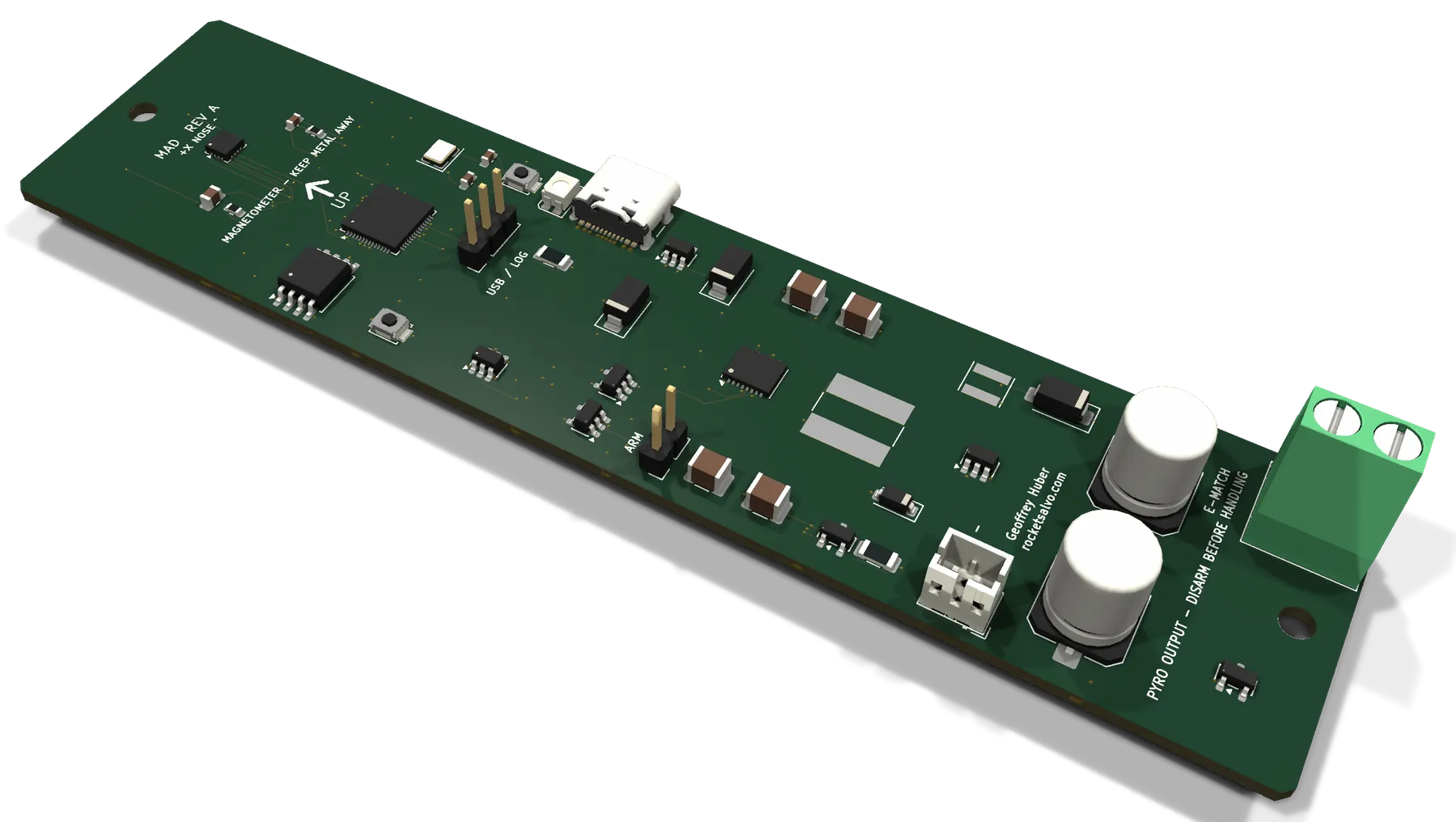
The board
Design
01
An MMC5983MA magnetometer measures the field along the rocket’s long axis. Orientation is the sole apogee cue; voltage readings are safety interlocks and telemetry only.
02
A removable ARM jumper is part of both the charger-enable and fire-enable hardware paths. Firmware cannot bypass it.
03
A capacitor bank drives one electric match. The firing charger is supplied from the battery regulator, so USB power alone cannot charge the bank.
04
SAFE → QUALIFY → ARMED → FIRING → LOCKOUT, with any detected fault forcing FAULT. A single firing pulse is followed by lockout until reset.
05
Flight data is logged to on-board flash and read back over USB-C, which is also used for configuration.
06
The Rev A design accepts 3–18 V, including a single-cell LiPo, through a resettable fuse and reverse-polarity protection.
Safety state machine
Arming requires the physical jumper, stable power and capacitor readings, a qualification delay and a post-arm inhibit. A single firing pulse is followed by lockout until reset.
FAULTAny detected fault forces this state from any other.
Specifications
The first table describes the Rev A prototype design and may change. Nothing in the second table has been finalized.
| Rev A design (prototype, subject to change) | |
|---|---|
| Apogee sensing | MMC5983MA 3-axis magnetometer, I²C |
| Microcontroller | RP2040 |
| Supply input | 3–18 V, including 1S LiPo; JST-PH connector |
| Output | One electric-match channel, 5 mm screw terminal |
| Firing bank | 2 × 470 µF at a nominal 12 V |
| Arming | Removable ARM jumper in the charge and fire hardware paths |
| Log storage | 16 MB flash; 4 MiB append-only flight-log region |
| Configuration and log retrieval | USB-C, USB 2.0 full speed |
| Programming and debug | SWD header |
| PCB | Four-layer |
| Not yet finalized | |
|---|---|
| Board dimensions | To be determined |
| Mass | To be determined |
| Current draw and battery life | To be determined |
| Operating temperature range | To be determined |
| Flight envelope (altitude, velocity, acceleration) | To be determined |
| Apogee detection performance | To be determined |
| Price and availability | To be determined |
Development status
Architecture, calculations and the verification plan.